On this page
Drum brakes are commonly used on the rear wheels of passenger vehicles, although brake layouts vary. In this design, curved brake shoes sit inside a rotating drum. When the shoes press against the drum's inner surface, friction slows the wheel and turns motion into heat.
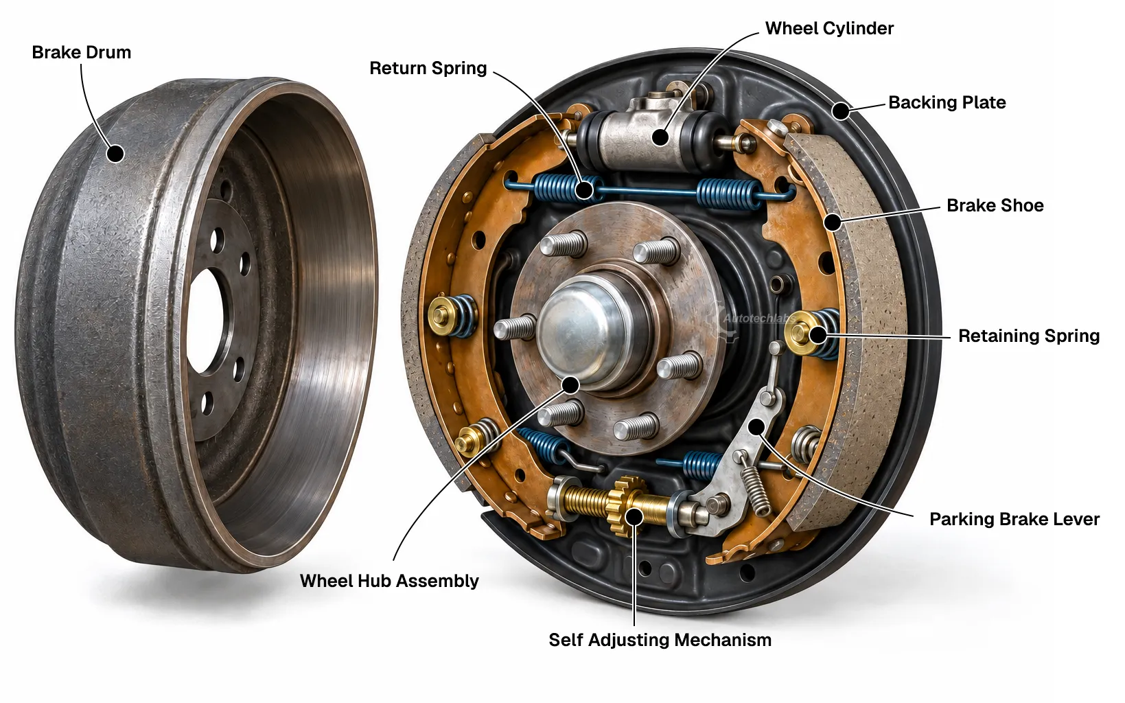
- Drum Brake Assembly -
Main components
The brake drum is attached to the wheel hub and rotates with the wheel. The backing plate supports the brake hardware. Two curved brake shoes, each carrying a friction lining, sit against the backing plate. Hold-down hardware keeps the shoes in position, while return springs pull them away from the drum after braking.
The lining is the friction material bonded or riveted to each shoe. It wears over time, and the drum's inner surface can also wear or become damaged. A worn, cracked, contaminated, or uneven brake assembly needs inspection using the vehicle manufacturer's service limits.
Wheel cylinder and braking action
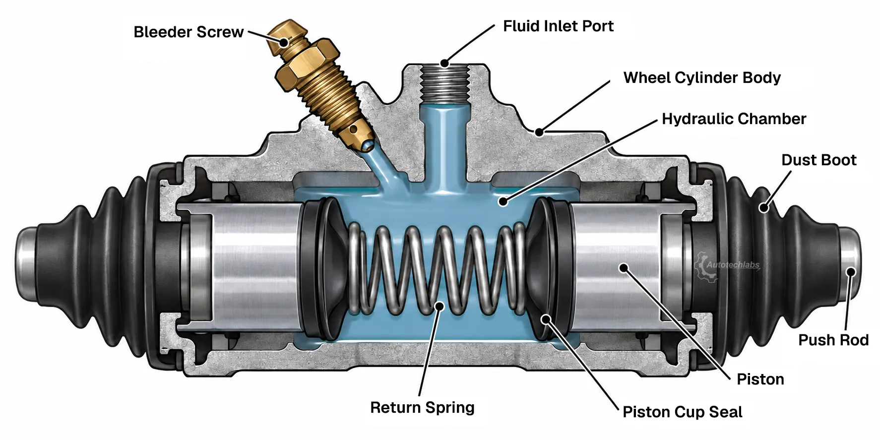
- Wheel Cylinder Cross-Section -
The wheel cylinder is a hydraulic actuator mounted at the top of many drum-brake assemblies. Brake fluid enters through its inlet. When the driver presses the brake pedal, hydraulic pressure moves pistons inside the cylinder outward. The pistons push the upper ends of the shoes against the drum. Friction between the linings and drum slows the wheel.
A typical wheel cylinder contains a cylinder body, two pistons, piston cups and expanders, a return spring, and protective dust boots. A bleeder valve allows trapped air to be removed during service. The exact internal arrangement can differ by design.
When pedal pressure is released, the shoe return springs pull the shoes back and the wheel-cylinder pistons return inward. This releases the drum so it can rotate freely with a small running clearance.
Self-adjusting mechanism
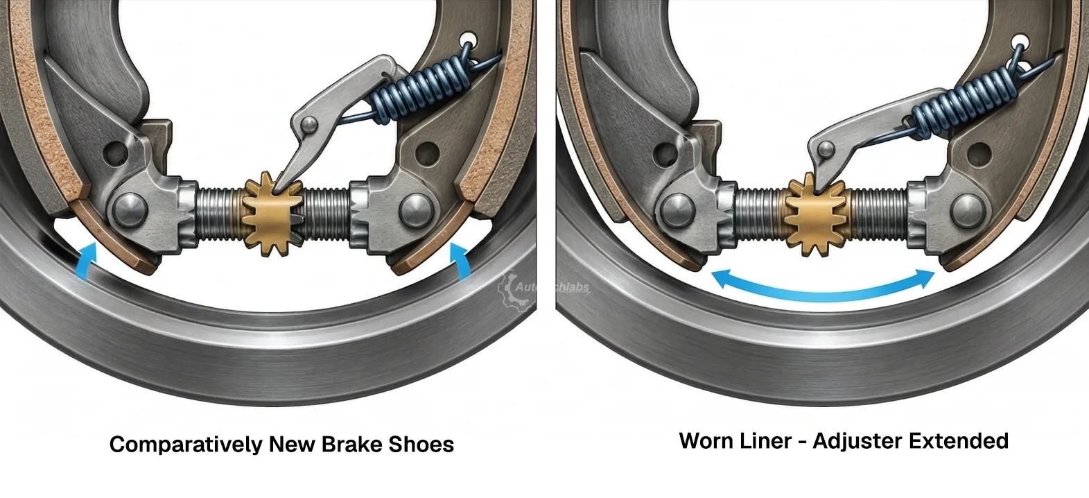
- Self-Adjuster Operation -
As the lining wears, the clearance between the shoes and drum can grow. A brake adjuster—often a threaded star-wheel mechanism—lengthens to bring the shoes closer to the drum. An adjuster lever and spring operate the ratchet on some designs. Many systems make an adjustment during suitable braking events, often when braking in reverse, but the trigger and mechanism vary by vehicle. The adjuster compensates for wear; it does not restore worn lining or replace inspection.
Parking brake
The parking brake holds the vehicle stationary while parked. In a cable-operated system, the hand lever or pedal pulls a cable connected to the rear brake hardware. At a drum brake, a lever and strut spread the shoes against the drum mechanically, independently of the service-brake hydraulics. Some vehicles with rear disc brakes use a small separate drum brake inside the rotor hat; others use a parking-brake mechanism built into the caliper.
An electronic parking brake (EPB) is commanded by a switch and controlled electrically. Depending on the vehicle, an electric motor may pull cables that operate rear brake hardware, drive actuators at the rear calipers, or operate another manufacturer-specific mechanism. An EPB is therefore not one single brake layout, and its service procedure is vehicle-specific.
Brake shoe lining thickness
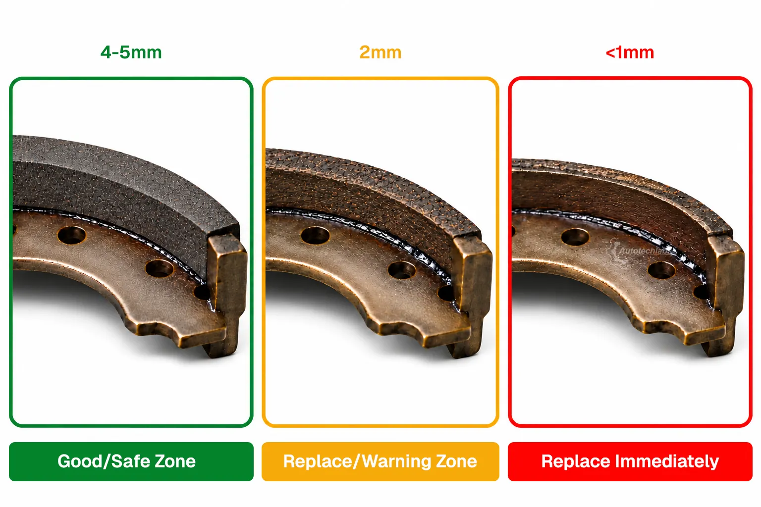
- Typical Passenger Vehicle Brake Shoe Lining Thickness Guide -
These approximate passenger-vehicle reference bands can help explain lining wear:
| Remaining friction lining | General indication |
|---|---|
| 4–5 mm | Generally considered safe when the shoes and drum are otherwise in good condition |
| About 2 mm | Marginal; arrange inspection and replacement planning promptly |
| Less than 1 mm | Dangerous; stop using the vehicle and have the brakes inspected immediately |
These bands are general guidance, not universal service limits. Published vehicle specifications vary: some manufacturers set a minimum around 1 mm, while others specify different limits. Follow the service information for the exact vehicle, measure the friction material rather than the metal shoe, and replace parts at or before the manufacturer's limit. Brake work is safety-critical; this overview is not a repair procedure.