On this page
A typical passenger-car service brake uses friction to slow the vehicle. When the brakes are applied, pads press against a rotating disc called a rotor. This friction converts some of the vehicle's kinetic energy into heat.
Many passenger cars use hydraulic service brakes at all four wheels, but brake layouts vary. A vehicle may use disc brakes, drum brakes, or both, and some vehicles also combine friction braking with regenerative braking. During deceleration, load shifts toward the front axle, so the front brakes typically handle a larger share of the braking work. The exact brake balance depends on the vehicle and its control systems.
Hydraulic system
The diagram below is a simplified model of hydraulic force transmission. In a typical vehicle, the brake pedal's leverage and a power booster, if fitted, increase the force applied to the master cylinder. The master cylinder converts that input into hydraulic pressure in the brake fluid.
Pascal's law describes how pressure applied to an enclosed fluid is transmitted through that fluid. In this idealized model, pressure at the two pistons is equal:
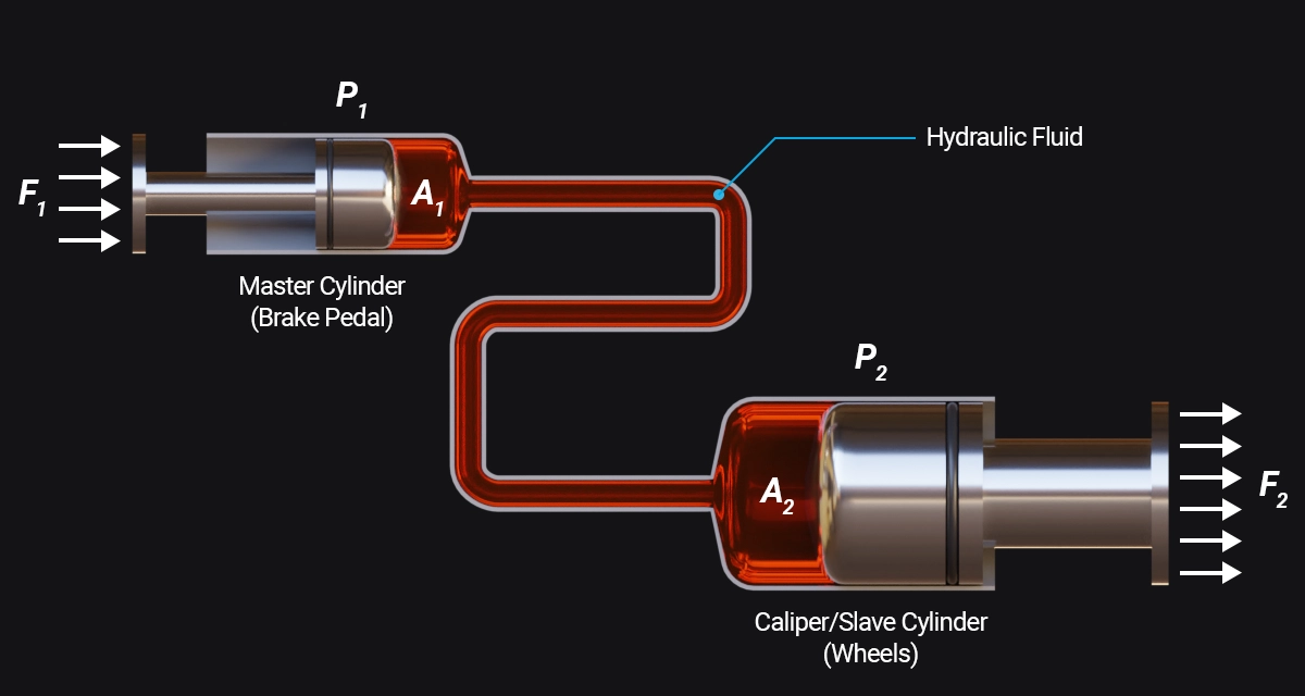
- Simplified Hydraulic System -
- F₁ — force applied to the master-cylinder piston
- F₂ — force produced at the output piston
- P₁ and P₂ — fluid pressure at each piston
- A₁ and A₂ — piston areas
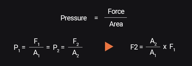
- Pascal's Law Equations -
For this simplified system, P₁ = P₂, and pressure equals force divided by area. A larger output piston can produce more force than the input piston, but it moves a shorter distance for the same volume of displaced fluid. In a vehicle, the pedal linkage, booster, hydraulic circuits, and electronic controls also affect how braking force is produced and distributed.
Disc brake caliper
In a disc brake, brake pads press against a rotor attached to the wheel. The exploded view below shows a single-piston floating caliper.
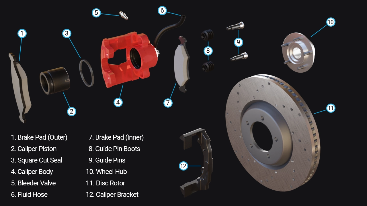
- Single-Piston Floating Caliper Assembly -
When the brake pedal is pressed, hydraulic pressure moves the caliper piston and pushes the inner pad against the rotor. The caliper body then slides along its guide pins, bringing the outer pad against the other side of the rotor. The two pads clamp the rotor and create friction, slowing the wheel.
This sliding action applies to floating calipers. Fixed calipers use pistons on both sides of the rotor and do not slide along guide pins. Caliper designs and piston counts vary; piston count by itself does not determine a vehicle's stopping performance.
When brake pressure is released, the piston seal's elastic recovery lets the piston move back slightly, leaving a small clearance between the pads and rotor. As pads wear, the piston advances through the seal to maintain its position. Clips or springs may also guide or retain the pads, depending on the design.
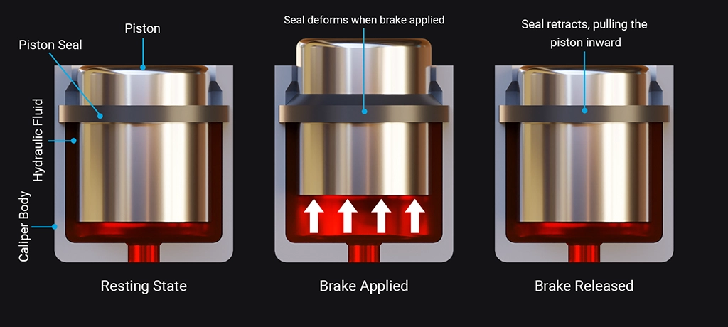
- Square-Cut Piston Seal Movement -
Brake fluid and air in the system
Brake fluid transmits pressure through the hydraulic system. Air is more compressible than brake fluid, so air in the system can cause a longer-traveling or soft pedal and can reduce braking performance. If air may have entered the system during repair, the brakes need to be bled using the procedure for that specific vehicle. The method and sequence vary, and some anti-lock braking systems require additional steps. Brake work is safety-critical; this overview is not a repair procedure.
Disc brakes and drum brakes
Both disc and drum brakes slow a vehicle through friction. In a drum brake, curved shoes press against the inside of a rotating drum. In a disc brake, pads press against the faces of a rotor.
Because a disc brake's friction surfaces are more exposed to airflow, disc designs generally shed heat more readily than comparable drum designs. This can help reduce brake fade during repeated heavy braking. It does not mean every disc-brake vehicle stops in a shorter distance: stopping performance also depends on the complete brake system, tires, road surface, temperature, and vehicle controls.
Some vehicles use disc brakes at all four wheels; others combine front discs with rear drums. Parking-brake mechanisms also vary by vehicle and may be separate from, or integrated with, the service-brake assembly.
Continue the series with Part 2: Master Cylinder and Brake Booster.