On this page
Part 1 explains how disc brakes use hydraulic pressure at the caliper. This part looks at how a typical tandem master cylinder supplies that pressure and how a brake booster can reduce the force the driver needs to apply at the pedal. Brake-system designs vary by vehicle.
Tandem master cylinder
A tandem master cylinder has two pistons arranged in one cylinder bore. Each piston pressurizes a separate hydraulic circuit. This split design is used in many vehicles so that a single circuit failure does not necessarily remove all service braking. The required design depends on the vehicle and the market where it is sold.
In a typical four-wheel passenger-car layout, the two circuits may be divided front-to-rear or diagonally, with each circuit serving two wheels. The master cylinder's outlet ports and the way lines are routed can vary; in some designs, a hydraulic control unit distributes pressure downstream. The diagrams show one simplified tandem-cylinder layout.
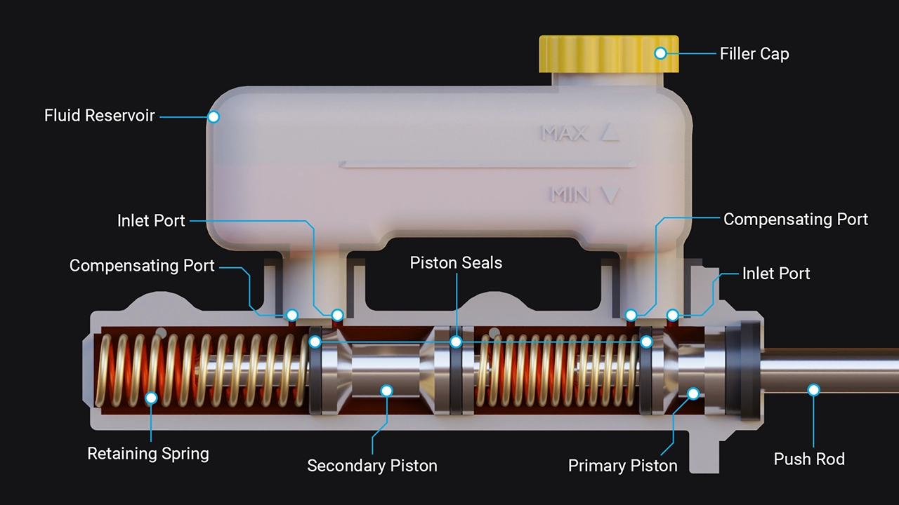
- Simplified Tandem Master Cylinder -
When the brake pedal moves the pushrod, it advances the primary piston. That piston closes its compensating port and pressurizes fluid in one circuit. Pressure also moves the secondary piston, which closes its port and pressurizes the other circuit. When the pedal is released, the return springs move the pistons back, pressure falls, and the ports allow the fluid volume to equalize with the reservoir.
If one circuit loses pressure
If one circuit cannot build pressure, its piston may travel farther than usual until it contacts another piston or reaches a mechanical stop. That movement allows the other circuit to build pressure. The exact piston movement depends on which circuit has failed and on the master-cylinder design.
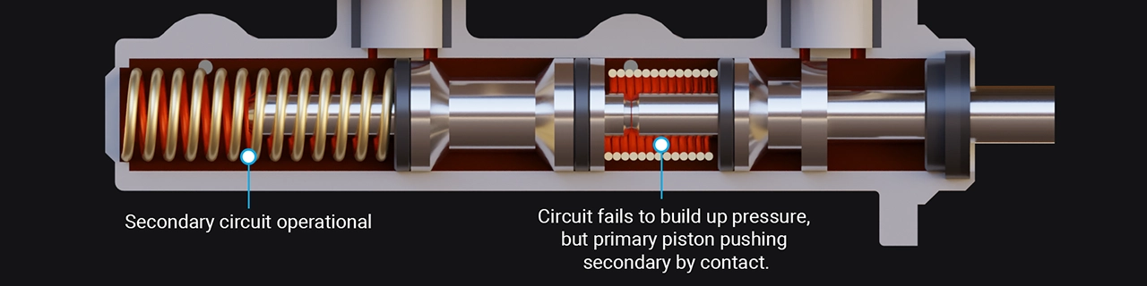
- Primary Circuit Failure -
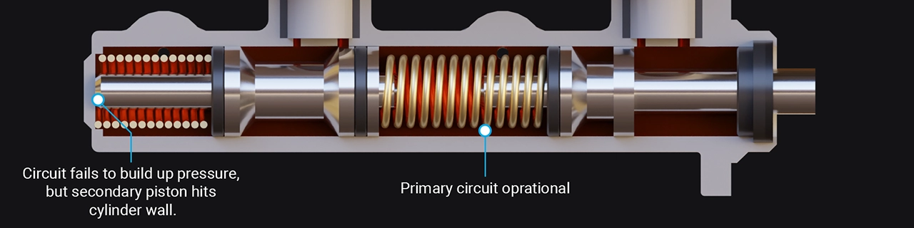
- Secondary Circuit Failure -
A split circuit can preserve some braking after a single-circuit failure, but braking performance may be greatly reduced. A brake-system failure is serious; the remaining circuit or parking brake is not a substitute for proper repair. Parking-brake designs vary and may be mechanically or electrically actuated.
Brake booster
A brake booster reduces the pedal effort needed to apply the brakes. In a common vacuum-assisted design, the booster sits between the pedal and master cylinder. When the driver presses the pedal, a valve admits air to one side of a diaphragm while the other side remains at lower pressure. The pressure difference moves the diaphragm and output rod, adding force to the master-cylinder pushrod.
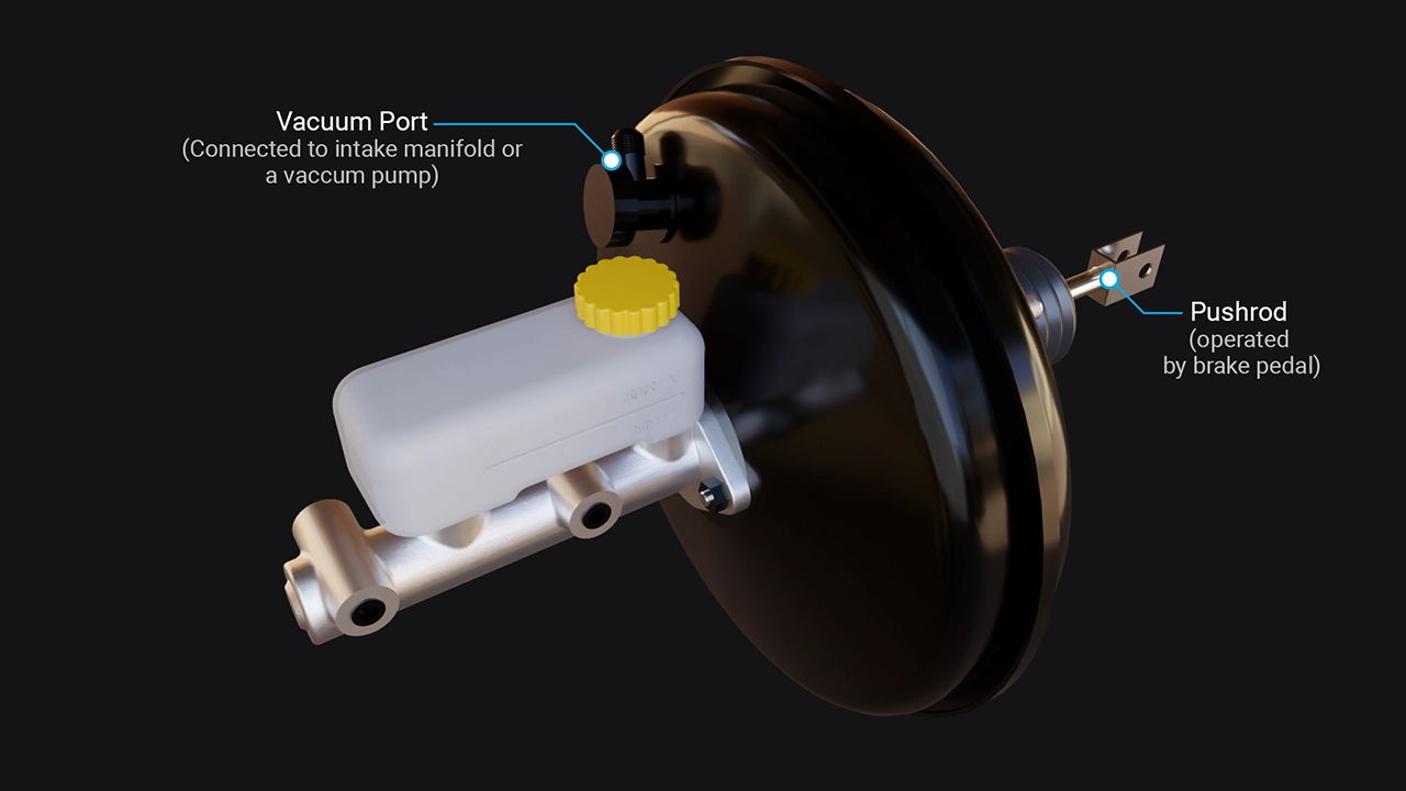
- Master Cylinder with Brake Booster -
Some vacuum-assisted systems draw vacuum from the engine; others use a separate vacuum pump. Vehicles that do not use vacuum assist may use electric or electrohydraulic brake-assist systems. The source of assist and the system layout depend on the vehicle.